We are seeing more aluminium extrusions in automotive applications like body parts, chassis components and battery housings. These applications tend to have medium to high strength, and good ductility to meet the requirements related to crash behavior. The typical hollow extruded profile can have many chambers and be relatively thin-walled to minimize material usage.
This is all good, but there is an issue: In the extrusion process, high-strength and ductile aluminium alloys normally need rapid cooling to achieve the product properties required. And when these alloys also contain end-of-life recycled aluminium, you have a combination of factors that affect the geometrical stability of the extruded profile. This makes it harder to gain the tolerances needed without excessive machining.

What I will do is present the strategies and methods for the calibration of automotive extrusions manufactured with these “new” alloys, then show you how tight automotive tolerances can be achieved from the extruded profile without machining by selecting the correct calibration method.
What is aluminium extrusion calibration?
Due to the nature of the extrusion process, geometrical variations tend to be larger than in alternative forming processes like sheet rolling. These variations make it difficult to meet the requirements of many automotive products without further refinements, such as by machining. And this can be expensive.
Aluminium extrusion calibration as an alternative to machining represents an attractive way to be able to meet tight geometrical tolerances.
Common geometric distortions in extruded aluminium profiles
Hollow aluminium extrusions show geometrical distortions and variations of the extruded geometry. These can be split into variations along the length of the profile and variations to its cross-section. Along the length of the profile, these variations are seen as bow or twist, while in the cross-section of the profile, we will see deviations in height, width, or straightness of the exterior profile walls.
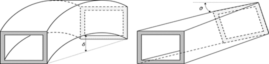
What this means is that for tight assemblies like battery boxes, profiles with such variations cannot be welded together to form a frame without excessive machining. In addition, hollow profiles also experience convexity and concavity, which makes initially straight profile members curve either inwardly or outwardly, thereby complicating welding and tightening of the frame.
Introducing plasticity to the aluminium extrusion
One way to overcome the need for additional machining is calibration, by introducing plasticity to the extruded profile. We prefer to do this before ageing to strength, to keep springback low.
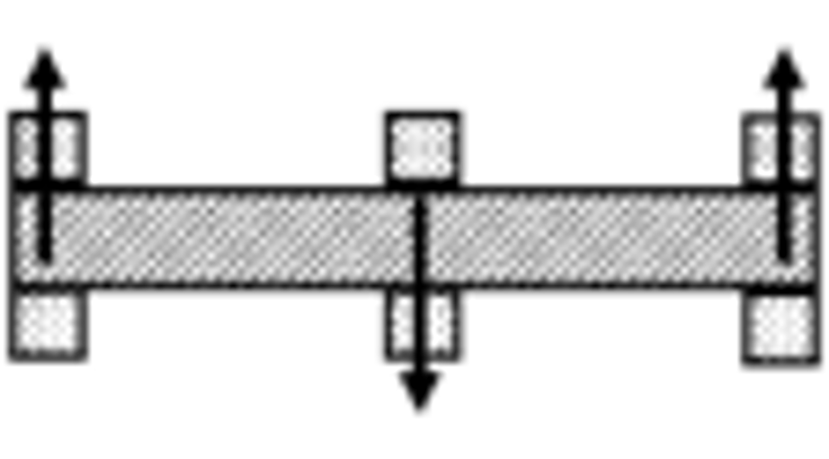
Over the years, several methods have been proposed. The most common method is to stretch the profile. This is being done today as an integral part of the extrusion process on the shop floor. By stretching the profile around 0.5%, we can reduce the bow and twist in the profile. It can also be performed on cut-to-length profiles for even better accuracy. However, a major drawback is that the gripping needed to stretch the profile introduces variations in the cross-section along the profile.

For a high degree of stretching, the contraction of the profile in the middle will be large compared to the original profile shape. For example, by stretching 2.5% in the extrusion direction, the contraction can be expected to be half of this in the transverse direction. For a 100mm high/wide profile, this would give a roughly 1.25mm smaller profile in height/width in the middle section.
Another method is to deform the profile from the outside, by applying a local force at certain points along the profile, bending the profile to the correct shape. Such a method is naturally very sensitive to storage time after extrusion, which influences the strength of the profile. These variations, together with large bending moments from the transverse loading situation, give high springback. Several application points along the profile will reduce the elastic springback, but the sensitivity to mechanical properties will remain high. Another drawback with such a method, also including the stretch calibration mentioned, is the inability to correct cross-sectional variations.
Compression, expansion and hydro calibration: removing surface deviations
The methods available for relocation of surfaces are compression, expansion, and hydro calibration. Each involves bringing the cross-section into plasticity, to stretch or compress the individual walls transversely in a way that straightens these out. Once the walls are straightened and stretched or compressed to the correct location, the springback will theoretically be low. This can be explained by the lack of bending moments, which will not be present in a straight wall under pure compression or pure stretching.
High-strength alloys, or alloys with a high content of post-consumer scrap, can be susceptible to variations in yield strength after extrusion. Ideally, profiles are calibrated directly after solutionizing, as this will give a very low yield strength and low elastic springback.

Compression calibration as an alternative
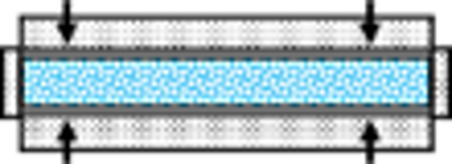
An alternative method for profile calibration is what we call compression calibration. In this, the profile cross-section is compressed into plasticity over the entire length toward non-expanding mandrels inside the profile. This method requires extrusion of a larger dimension than the intended one, and the extruded product is compressed to the final shape in the calibration process.
As the periphery of the profile is formed into plastic compression, the location of the outer surfaces can be controlled by the location of the tool parts used from the outside, hence reducing the influence of the wall thickness with respect to the location of the outer surfaces. Additionally, bow and twist will be removed from the extruded profile as in the concept with the expanding mandrels.
A drawback with this method is that long mandrels must be machined and adapted to each profile geometry, which creates cost and complexity to the calibration. It can also be a challenge to remove the mandrels from the profile after forming. Compression calibration with mandrels is normally performed in a hydraulic press.
Expansion calibration to remove bow and twist
Calibration methods able to remove bow and twist and to correct the cross-sectional deviations typically involve expanding the cross-section by the application of mandrels from inside the profile.
It is done in this way: The mandrels are placed inside the profile and then moved apart by a wedge mechanism. As the mandrels are moved, the exterior profile walls move away from the center line, and the length of the periphery will increase and deform plastically. This can also potentially remove bow and twist, and calibrate the location of the surfaces to each other.
A drawback with this method is the application of long and mechanically complex mandrels, which are expensive to make and prone to breaking because of high forces. For multi-chamber extrusions, especially non-symmetrical ones, the design and operations of the mandrels will be complicated. The initial profile must be smaller than the final profile after calibration to accommodate the expansion process.
Using liquid in hydro calibration
To avoid the complexity of having profile-specific mandrels inside the profile, we propose hydro calibration – an alternative method where a liquid supports the profile during calibration.
In this method, the profile to be calibrated is placed completely in the liquid, or alternatively filled up internally by a liquid, like in hydroforming. The ends of the profile are then closed or partly closed, either by a device going inside the profile walls or just by flat surfaces pressed toward the profile ends. The outer dimensions of the extruded profile are larger than the final intended shape, being enclosed by tool surfaces that will be moved together.
Upon pressing the tool surfaces towards the extruded profile, the volume inside the profile will decrease and create pressure inside the profile. Unlike in hydroforming, where an external pump creates the pressure needed to expand the profile toward the tooling surfaces, the tool surfaces themselves are creating the internal pressure by performing a compressive action toward the exterior profile walls. The internal pressure will act like mandrels and prevent the exterior profile walls from leaving the tool surfaces and hence avoid deformation of any exterior profile wall being supported by the outer tool surfaces.
The calibration method is finalized once the outer profile surfaces in contact with the tool have reached the desired position. This removes distortions of the profile like bow and twist, and relocates the exterior of the profile to the desired position. As no mandrels are placed inside the profile, only the devices closing the profile ends and the enclosing tool parts must be moved away to release the profile after calibration. As the tools are released, the elastic energy stored in the profile from the calibration will be released.
A cost-efficient solution to achieve tight tolerances
In addressing these calibration methods, and some of their pros and cons, we can conclude that stretching a profile is the best and simplest way to remove bow and twist, whereas more tooling-intensive methods like compression, expansion or hydro calibration is needed for stable calibration of any types of geometrical distortion.
Again, for high-strength alloys, tight tolerances for automotive applications can be difficult to meet only by the extrusion process itself. In this case, hydro calibration represents a cost-efficient alternative to address reduced variation of the final profile – both for relocation of surfaces and for reducing bow and twist.
Comparison of five aluminium extrusion calibration methods: stretching, external point loading, expansion, compression, and hydro calibration.
|
Calibration method |
Illustration |
Remove bow and twist |
surfaces |
Single- chamber profiles |
Multi- chamber profiles |
High machine investment |
Tooling intensive |
|
Stretching |
|
Yes |
No |
Yes |
Yes |
No |
Small |
|
External point loading |
|
Yes |
No |
Yes |
Yes |
Yes |
No |
|
Expansion |
|
Yes |
Yes |
Yes |
Limited |
Yes |
Yes |
|
Compression |
|
Yes |
Yes |
Yes |
Yes |
Yes |
Yes |
|
Hydro calibration |
|
Yes |
Yes |
Yes |
Yes |
Yes |
Small |